
AUTOMATING PERTURBATION EXPERIMENTS USING A CABLE-DRIVEN IMPEDANCE HAPTIC DEVICE
UW MS Thesis
Designing a Cable Driven Haptic Testbed for the four-linkage hopping robot
SUMMARY
Motivation & Goal
Need for testing/perturbing robots in a systematic method
Need for testing robots in different enviorments
Design a testbed that can render virtual dynamics to emulate different environments on a robot and perturb it in systematic/repeatable method.
Mechanical Design
Designing (Inventor/SolidWorks)
Prototyping (Laser cutter: acrylic)
Fabricating (Mill, lathe, other hand tools)
Force Control
Implemented a force control controller for the nonlinear system. Experimental procedure as follows
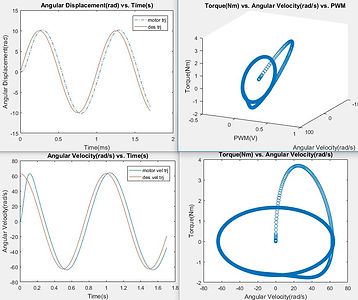
1. Experimentally measure torque across the range of vel and PWM
2. Gaussian Process to train the model
3. Calibrate acceleration to force using a load cell
System Characterization
Characterized the performance of the haptic device setup. Experimental procedure as follows
1. Experimentally measure the force and velocity using sum of sines trajectory on bottom motor
2. Apply FFT on the input/output of the signal and find the transfer function
3. Apply the transfer function on a hopper’s velocity data to find out the force error
Testing the haptic device
Tested the haptic device with the hopper into loop. This testbed will not only allow the user to perturb the robot but also simulate the environment. For example, by applying constant positive force (upward), it can reduce the effect of gravity and simulate the robot's dynamics when jumping on the moon. This is a novel approach to simulate the environment through hardware. It can be extended to multi DOF to for more complex robots.

MECHANICAL DESIGN
Cable driven system with pulleys to redirect the force.
Prototyped using a laser cutter and acrylic
Fabricated parts of the testbed using lathe, mill, and other hand tools after modeling it on Autodesk Inventor/SolidWorks.
LINEAR MODEL
Implemented a linear model for the brushless DC motor to positive feedback angular velocity to cancel the back-EMF of the motor as well as control the torque via PWM.
Simulated the back-EMF cancellation model on MATLAB considering voltage, current saturation and inertia of the system.
Trajectory generation/planning to populate the space of the torque speed curve with data from the testbed
System behaves nonlinear

FORCE CONTROL
Used model-based force control
Experimentally measured torque across the range of velocity and PWM
Used linear regression to find acceleration from velocity data
Used Gaussian process to train the model and generate a surface
Integrated a load cell, multimeter, and oscilloscope to calibrate acceleration to force
SYSTEM CHARACTERIZATION
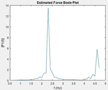
Quantify how well the force control is performing for the haptic system by finding the force errors over the range of frequencies the hopper resides
Experimentally measure the force and velocity using sum of sines trajectory on bottom motor
Apply FFT on the input/output of the signal and find the transfer function
Apply the transfer function on a hopper’s velocity data to find out the force error
With the haptic device applying net force of 0N, the magnitude of force error the haptic system will apply to the robot will be around 13N.


thesis
thesis


hopper

13N
20180601_004444
